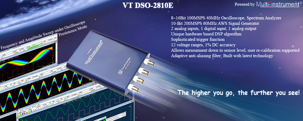
PC based USB 8~16Bit 100MSPS 40MHz Oscilloscope, Spectrum Analyzer, 10-bit
200MSPS 60MHz
AWG Signal Generator Brochure Manual Manual
US$349.95
Free Express
Shipping
Download and try the fully functional Multi-Instrument software using your sound card as the ADC and DAC device!
1. Instroduction
This is one of the second-generation USB DSOs
(USB oscilloscopes) designed and developed by Virtins Technology. This generation of USB DSOs features Virtins Technology’s unique hardware-based DSP algorithm which enhances the performance and functionality dramatically without adding extra hardware cost. When used in conjunction with Multi-Instrument® software, the USB DSO converts any desktop, laptop, or tablet PC into a powerful oscilloscope, spectrum analyzer, multimeter, data logger, signal generator and so forth, all of which work simultaneously.
2. Package Contents
1) VT DSO-2810E unit with a hardware bundled
Multi-Instrument
Standard software license
2) 2 × 60MHz Oscilloscope Probe
P2060 with two switchable positions: × 1, × 10
3) Signal
Generator Test Lead (1 m)
4) USB cable (1.5 m)
5) CD
(contains the copy-protected Multi-Instrument Software and VT
DSO-2810E driver)
6) Individual voltage calibration data
|
|
3.
VT DSO-2810E Hardware Specifications
| Oscilloscope Horizontal
(Time) Axis |
| Real Time Sampling
Frequency (fs) |
Single Analog Channel
100 MHz
Single or Dual Analog Channels with
or without 1-bit Digital Channel
50 MHz, 40 MHz, 20
MHz, 10 MHz, 5 MHz, 4 MHz,
2 MHz, 1 MHz, 500 kHz, 400 kHz,
200 kHz, 100 kHz,
50 kHz, 40 kHz, 20 kHz, 10 kHz, 5 kHz, 4
kHz, 2 kHz,
1 kHz, 500 Hz, 400 Hz, 200 Hz, 100 Hz, 50 Hz, 40
Hz,
20 Hz, 10 Hz, 5 Hz, 4 Hz, 2 Hz, 1 Hz |
| Equivalent Sampling
Frequency |
= [Real Time Sampling
Frequency] × [Number of Frames Persisted]. Maximum 20 GHz, for
repetitive signals whose maximum frequency is less than ¼ of the
real time sampling frequency. Not valid for the case of
post-trigger. |
| Buffer Size |
Normal Frame Mode |
Analog |
Single
Channel
40000 samples (8 bits)
20000 samples (16 bits)
Dual Channels
20000 samples / channel (8 bits, Non-ALT
mode)
10000 samples /
channel (16 bits, Non-ALT mode)
40000 samples / channel (8
bits, ALT mode)
20000 samples / channel (16 bits, ALT mode) |
| Digital |
20000 samples (1 bit) |
Record Mode
(Streaming Mode) |
Limited only by hard disk
space available and maximum file size allowed by the operating
system.
Maximum sampling frequency for continuous streaming
is computer speed and software setting dependent and typically
10
MHz (single channel, 8 bit) in Multi-Instrument. |
Roll Mode
(Streaming Mode for Low
Frequency Signals) |
Limited only by the
computer memory available.
Roll Mode is allowed when fs
≤ 1MHz and [Record Length]
≥ 4 × [Roll Width]. Maximum sampling
frequency for continuous streaming is computer speed and
software setting dependent. |
| Sweep Time |
10 ns ~ 500 s
(Non-Streaming Mode) |
| Sampling Frequency Accuracy |
± 50 ppm |
| Oscilloscope Vertical
(Analog) Axes |
| Number of Channels |
2 (i.e. Ch. A and Ch. B) |
| ADC Bit Resolution |
8 Bits |
Enhanced ADC Bit Resolution
(available only when Sampling Frequency is less than 40 MHz) |
16 Bits
If this option
is selected, the effective bit resolution increases from 8 bits
to up to 16 bits as the sampling frequency goes down.
(Assuming white noise in the signal) |
| Sampling Frequency |
Effective Bit Resolution |
Sampling Frequency |
Effective Bit Resolution |
| ≥ 40 MHz |
8 Bits |
≤ 10 MHz |
9 Bits |
| ≤ 2.5 MHz |
10 Bits |
≤ 625 kHz |
11 Bits |
| ≤ 156 kHz |
12 Bits |
≤ 39 kHz |
13 Bits |
| ≤ 9.8 kHz |
14 Bits |
≤ 2.4 kHz |
15 Bits |
| ≤ 610 Hz |
16 Bits |
|
|
| Bandwidth |
fs > 20 MHz |
40 MHz |
| fs ≤ 20 MHz |
8 Bits |
No Effective Bit Resolution
Enhancement |
40 MHz |
| Effective Bit Resolution
Enhancement |
6 ~ 10 MHz |
| 16 Bits |
Effective Bit Resolution
Enhancement |
about 0.443 fs |
Voltage Measuring Range
(Full Scale) |
± 10 mV, ± 20 mV, ± 50 mV,
± 100 mV, ± 200 mV, ± 500 mV, ± 1 V, ± 2 V, ± 5 V, ± 10 V, ± 20
V, ± 50 V |
| Max. Allowed Voltage |
± 100 V (DC + AC peak), derated above 100kHz |
| DC Accuracy |
± 1% |
| Coupling Type |
AC / DC |
| Input Isolation |
No (Isolation can be
achieved through a USB isolator) |
| Terminal Type |
Referenced Single-Ended,
BNC |
| Input Impedance |
1 MΩ , 15 pF |
| Zero Calibration |
Through hardware.
Individually done at factory, user adjustable |
| Gain Calibration |
Through hardware.
Individually done at factory, user adjustable |
|
Oscilloscope Vertical
(Digital) Axis |
| Number of Channels |
1 (i.e. External Trigger Channel, 1-bit
ADC) |
| Bandwidth |
140 MHz |
| Threshold Resolution |
45 mV |
| Threshold Hysteresis |
225 mV |
| Threshold Range |
± 20 V |
| Max. Allowed Voltage |
± 100V
(DC + AC peak), derated above 100kHz |
| Threshold DC Accuracy |
± 1% |
| Coupling Type |
DC |
| Input Isolation |
No (Isolation can be achieved through a
USB isolator) |
| Terminal Type |
Referenced Single-Ended, BNC |
| Input Impedance |
1 MΩ , 15 pF |
| Zero Calibration |
Through software. Individually done at
factory. |
| Gain Calibration |
Through software. Individually done at
factory. |
|
Oscilloscope Trigger |
| Trigger Detection Method |
Digital |
| Trigger Source |
Ch. A, Ch. B, EXT, ALT |
| Trigger Mode |
Auto, Normal, Single, Slow |
| Trigger Edge |
Rising, Falling |
| Trigger Level |
Adjustable within full scale |
| Pre-Trigger |
-100% ~ 0% of Record Length |
| Post-Trigger |
0 ~ 100% of Record Length |
| Trigger Frequency Rejection |
Nil: No Rejection
HFR: High
Frequency Rejection, cut off at 0.11fs
NR0: Noise Rejection,
hysteresis = 1% of half of full scale
NR1: Noise Rejection,
hysteresis = 2% of half of full scale
NR2: Noise Rejection,
hysteresis = 4% of half of full scale
NR3: Noise Rejection,
hysteresis = 8% of half of full scale
NR4: Noise Rejection,
hysteresis = 16% of half of full scale
HN0: HFR + NR0
HN1:
HFR + NR1
HN2: HFR + NR2
HN3: HFR + NR3
HN4: HFR + NR4
HNX: selectable HFR + adjustable hysteresis = 0% ~ 25% of half
of full scale
Note: The specified hysteresis may be modified
internally to ensure [Trigger Level (%)] – [Hysteresis (%)] ≥ -100% at rising edge, or [Trigger Level (%)] + [Hysteresis (%)] ≤ 100% at falling edge. |
|
Oscilloscope Dynamic
Performance (Typical) |
| THD |
fs=100 kHz, f=1 kHz, from 2nd to 20th
order, full-scale input:
8 bits (without bit resolution
enhancement):
≤ -55 dB
8 bits (with bit resolution enhancement):
≤ -56 dB
16 bits:
≤ -59 dB |
| IMD (250 Hz + 8 kHz, 4:1) |
fs=100 kHz, from 2nd to 3rd order,
full-scale input:
8 bits (without bit resolution enhancement):
≤ -51 dB
8 bits (with bit resolution enhancement):
≤ -52 dB
16 bits: ≤ -57 dB |
| IMD (19 kHz +20 kHz, 1:1) |
fs=100 kHz, 2nd order only, full-scale
input:
8 bits (without bit resolution enhancement):
≤ -65 dB
8 bits (with bit resolution enhancement):
≤ -65 dB
16 bits:
≤ -78 dB |
| SFDR |
fs=100 kHz, f=1 kHz, full-scale input:
8 bits (without bit resolution enhancement):
≥ 61 dB
8 bits (with bit resolution enhancement):
≥ 61 dB
16 bits:
≥ 62 dB |
| Crosstalk |
≤ -45 dB (at the same voltage measuring range for full
bandwidth) |
| Noise |
For voltage measuring ranges ± 50 mV
and above:
8 bits (without bit resolution enhancement):
≤ ± 3 counts (± 1%)
8 bits (with bit resolution
enhancement, fs =100 kHz):
≤ ± 2 counts (± 0.8%)
16 bits (fs =100 kHz):
≤ ± 0.3 8-bit count (± 0.1%)
For voltage measuring
ranges ± 10 mV and ± 20 mV:
8 bits (without bit resolution
enhancement):
≤ ± 15 counts (± 6%)
8 bits (with bit resolution
enhancement, fs =100 kHz):
≤ ± 9 counts (± 4%)
16 bits (fs =100 kHz):
≤ ± 1 8-bit count (± 0.4%) |
|
Signal Generator General
|
| Number of Channels |
1 |
| Coupling Type |
DC |
|
Output Isolation |
No |
| Terminal Type |
Referenced Single-Ended, BNC |
| Output Impedance |
50 Ω |
| Overvoltage
Protection |
± 35 V |
|
Signal Generator -Analog
(when Signal Generator is running) |
| Output Voltage Range |
± 2 V, adjustable |
| DAC Bit Resolution |
10 Bits |
| Output Sampling Frequency
(fs) |
DDS Mode
200 MHz, 100MHz, 50MHz
DDS Mode or Streaming
Mode
20MHz, 10MHz, 5MHz, 2 MHz, 1 MHz, 500 kHz, 200 kHz, 100 kHz, 50 kHz,
20 kHz, 10 kHz, 5 kHz |
| Output Sampling Frequency
Accuracy |
± 50 ppm |
| Bandwidth |
DC ~ 60 MHz |
| Output Signal Frequency |
0 ~ ½ of output sampling frequency |
| Rise Time (10% ~ 90%) |
< 5.8 ns |
| DC Offset Range |
Full output voltage range |
| DC Accuracy |
± 0.5% of full scale |
| Waveform |
DDS Mode* |
Sine, Rectangle (duty cycle
adjustable), Triangle, Saw Tooth,
White Noise, MLS (length =
263-1), User
Configurable Waveform Library (Arbitrary), Musical Scale |
| Streaming Mode* |
Sine, Rectangle (duty cycle
adjustable), Triangle, Saw Tooth,
White Noise, Pink Noise,
MultiTones, MLS (127~16777215), DTMF, User Configurable Waveform
Library (Arbitrary), Musical Scale |
Signal Frequency Resolution
|
DDS Mode |
<0.05 Hz (fs = 200 MHz)
<0.000001 Hz
(fs = 5 kHz) |
| Streaming Mode |
Virtually infinitesimal |
| Buffer Size |
DDS Mode |
Without interpolation: 1024 samples
With interpolation: 1024 × 65536 = 67108864 samples
(Note:
interpolation is only available when fs <= 100 MHz) |
| Streaming Mode |
Virtually unlimited |
| Frequency Sweep |
DDS Mode |
Supports linear sweep of all types of
repetitive waveforms.
Sweep speed range: 1/32768 × fs2
/ 232 ~ 65535 × fs2 / 232
(e.g. 284 Hz/s ~ 610 GHz/s when fs = 200 MHz) |
| Streaming Mode |
Supports linear and logarithmic sweep
of all types of repetitive waveforms.
Sweep speed range:
unlimited |
| Amplitude Sweep |
DDS Mode |
Supports linear sweep of all types of
waveforms.
Sweep speed range: 1/32768 × fs / (232 –1) ~
65535 × fs / (232 –1)
(e.g. 0.000142 %/s ~ 305171%/s when fs = 200 MHz) |
| Streaming Mode |
Supports linear and logarithmic sweep
of all types of waveforms.
Sweep speed range: unlimited |
| Duration (Signal Length)
Resolution |
DDS Mode |
1/fs or 1µs, whichever is greater |
| Streaming Mode |
1/fs |
| THD |
≤ -60 dB
(fs = 2 MHz, f = 1 kHz, from 2nd to 20th
order, full-scale output) |
| SFDR |
≥ 65 dB
(fs = 2 MHz, f = 1 kHz, full-scale output) |
| Zero Calibration |
Through software. Individually done at
factory. |
| Gain Calibration |
Through software. Individually done at
factory. |
*DDS mode consumes almost no computer CPU time while streaming mode
consumes a lot. Maximum sampling frequency for continuous streaming is
computer speed and software setting dependent and typically 10 MHz
in Multi-Instrument. More advanced functions are provided via
Multi-Instrument software under streaming mode. Please refer to
Multi-Instrument software manual for details.
|
Signal Generator - Digital
(when Signal Generator is not running) |
| Voltage Range |
-1.65 ~ 1.65 V, not adjustable |
| Output Signal Frequency
Accuracy |
± 50 ppm |
| Bandwidth |
60 MHz |
| Rise Time (10% ~ 90%) |
< 5.8 ns |
| Waveform |
Square |
Signal Frequency |
25 MHz / N, (N=1, 2, 3, ….25000) |
| MLS |
Sampling Frequency |
25 MHz / N, (N=1, 2, 3, ….25000) |
|
General |
| Interface |
USB 2.0 High Speed / USB
1.1 Full Speed / USB Isolator |
| Device Category in
Multi-Instrument |
ADC Device |
VT DAQ 1 |
| DAC Device |
VT DAO 1 |
| Firmware Upgradable |
Yes |
| Power |
Bus powered by USB port, no
external power source required. |
| Power Consumption |
Max. 2.5W |
| Dimensions |
145 mm (L) × 108 mm (W) ×
26 mm (H), anodized aluminum case |
| System Requirement |
Windows XP, Vista, 7, 8,
8.1, 10 or
11, 32 bit or 64 bit |
| Operating Temperature |
0° C ~50° C |
4. P2060 Oscilloscope Probe Hardware
Specifications
| Attenuation Ratio |
× 1, × 10 |
| Bandwidth |
DC ~ 60 MHz (× 10), DC ~ 6 MHz (× 1) |
| Input Impedance |
1 MΩ (× 1, with VT DSO connected)
10
MΩ (× 10, with VT DSO connected) |
| Input Capacitance |
14 pF ~ 18 pF (× 10), 70 pF ~ 120
pF (× 1) |
| Input Capacitance Compensation Range |
15 ~ 45 pF |
| Length |
1.2 m |
Accessories include: a 12 cm snap-on rotating ground lead, a sprung
hook, two marker rings, a probe compensation adjustment tool, two probe
tip caps.
5. Examples
1)
Measurements of PAL Composite Video Signals
2) Measurements of a 500Hz sine wave and a 1kHz square wave under ALT
trigger mode
3) Mixed signal display. Channels A & B are analog input channels while
Channel EXT is used as a digital input channel
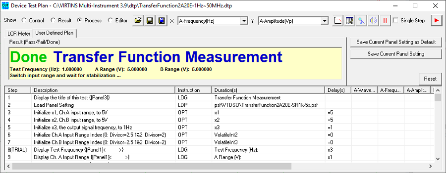
4) Transfer Function Measurement using Frequency Stepped Sine Signal from 1Hz to
25MHz and Auto Ranging Algorithm
(Device Test Plan required)
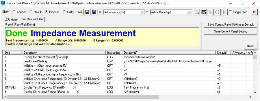
5) Impedance & Phase Measurement using Frequency Stepped Sine Signal from 1Hz to
25MHz and Auto Ranging Algorithm (Device Test Plan required)
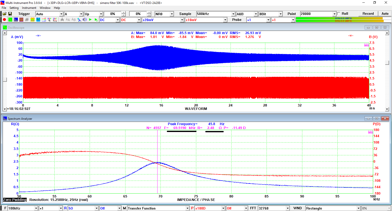
6) Impedance & Phase vs Frequency of a filter using swept sine from
50kHz to 100kHz (Multi-Instrument Pro required)

|
|